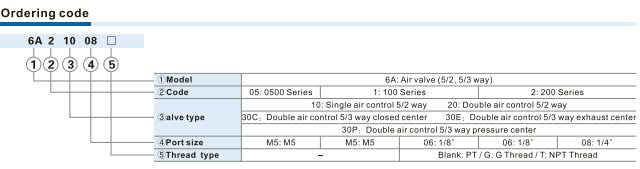
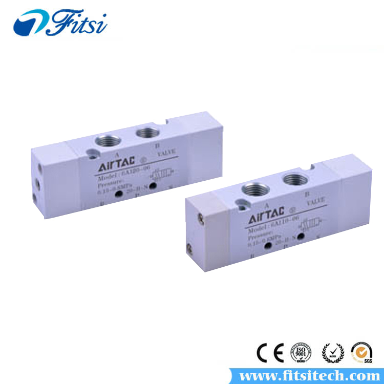

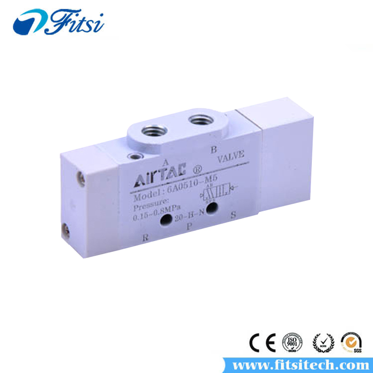

Product Name:6A Series Pneumatic Solenoid Valve
Product Model:6A0510 6A0520 6A0530 6A110 6A120 6A130 6A210 6A220 6A230
Valve Type:Solenold Valve, Pneumatic Control Valve
Brand:AirTAC
Fluid: Air
Acting: Exterior Control
|
Model: |
6A0510 |
6A0520 |
6A0530 | 6A110 | 6A120 | 6A130 |
| Port Size: |
In=Out=Exh=M5 |
In=Out=Exh=M5(OR=PT1/8) | ||||
| Orifice Size(Cv): | 5.0mm²(0.28) | 4.5mm²(0.25) |
M5:5.5mm²(0.3) |
|||
| 06:10mm²(0.58) | 06:8.5mm²(0.51) | |||||
| Max. Frequency: | 5 Cycle/Sec | 3 Cycle/Sec | 5 Cycle/Sec | 3 Cycle/Sec | ||
| Weight: | 20g | 25g | 30g | 50g | 60g | 65g |
|
Model: |
6A210 |
6A220 | 6A230 | |||
| Port Size: | In=Out=PT1/8(OR=PT1/4) Exh=PT1/8 | |||||
|
Orifice Size(Cv): |
06:14.0mm²(0.78) | 14.0mm²(0.82) | ||||
| 08:18.0mm²(1.06) | ||||||
| Max. Frequency: | 5 Cycle/Sec | 3 Cycle/Sec | ||||
| Weight: | 120g | 125g |
135g |
|||
| Fluid: | Air(to be filtered by 40μm filter element) | ||||||
| Acting: | Exterior Control | ||||||
| Operating Pressure: |
5/3 way |
0.2~0.8MPa(29~114psi) |
|||||
| 5/2 way | 0.15~0.8MPa(21~114psi) | ||||||
| Proof Pressure: |
1.2MPa(175psi) |
||||||
| Temperature: | -20~70℃ | ||||||
| Material of Body: |
Aluminum Alloy |
||||||
| Lubrication: | Not Required | ||||||
① PT thread, NPT thread and G thread are available.
②Once lubricated air is used, continue with same medium to optimise valve life span. Lubricants like ISO VG32 or equivalent are recommended.
③The maximum actuation frequency is the no-load state.
1. The boby is extruded by aluminum alloy, and the inner hole is specially processed to increase the flow rate.
2.Can integrate manifold to form valve group to save space.
Installation & Usage:
1.Before installing, be sure the valve hasn't been damaged via transportation.
2.It's suggested to use the medium lubricated by 40μm filter element. Be aware of the flow direction and port size.
3.Please notice whether the installation condition accords with technical requirements (such as“act-uation frequency”, “working pressure” and “scope of application temperature”), then the equipment can be installed and used.
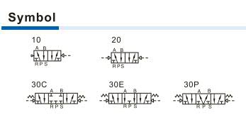
4.Notice the flow direction of air during installation, P is the air intake, A (B) is the work port and R (S) is the exhaust outlet.
5.Take measure to avoid vibration and frozen.
6.Firstly press the base gasket into the base, and then connect the base with the valve body by the affiliated screws. The base gasket can be pressed into the installation places that are not used temporarily, and then seal them with affiliated blank cap. When the system expands, take the blank cap off and install relative air valves;
7.To keep the dust away, please use the silencer for the exhaust ports. Never forget to install dirt-proof boot in air intake and outlet during dismounting.